

This article is for developers responsible for USoft implementations. It tells them how to interpret (= read) BPMN concept diagrams in USoft Studio so they understand better what is expected of them.
If you want to create BPMN concept diagrams, please go to the Home page of USoft Studio. On the Help tile, on the Diagrams tab, open the PDF document about BPMN diagrams.
What is a BPMN process flow diagram?
Business Process Model and Notation (BPMN) is a formal specification of the Object Management Group (OMG). As the OMG states, "the primary goal of BPMN is to provide a notation [of business process flow]" that is readily understandable by all business users, from the business analysts that create the initial drafts of the processes, to the technical developers responsible for implementing the technology that will perform those processes, and finally, to the business people who will manage and monitor those processes."
Here is a small example of a BPMN diagram as created in USoft Studio, followed by an explanation of what it depicts.

Events and activities
Each instance of this process starts with a catching message event, meaning that it occurs each time such a message comes in. This particular message contains a contractor's wish to rent a car. This could be literally a message (for example an e‑mail message), or it could involve a physical person ringing, or coming to a reception desk and pronouncing the message as a request. The process itself is a sequence of steps represented by rectangular boxes that name each step. The first step is to register the rental request, and so on.
Swimlanes
The drawing looks like a swimming pool with 2 lanes. There is a lane for the point of sale and a lane for the delivery desk. The activity "Register rental request" has no less than 2 arrows going out, one staying in the first lane and the other going into the second lane. This means that once the rental request is entered, two activities must take place concurrently. The point of sale that received the request must quote a price. The delivery desk must allocate a car. Once both are completed, the point of sale continues the process by getting a confirmation from the contractor.
Black-box pool
A BPMN process is a view of what must be done from the point of view of the "own" organisation. Exactly what external parties, such as customers or partners, do in the meantime is not depicted. Instead, external parties are shown as black-box pools. In this case, we do not see the activities of the contractor, but we do see the messages going back and forth between the contractor and the process.
Gateways
Diamond shapes called gateways show points where the process can go multiple ways depending on some outcome or decision. For example, the "Car available?" gateways tests whether the delivery desk was actually successful in allocating a rental car. If it was not, the step during which the rental request is registered must be redone. Exactly what this entails is not explicit - apparently it does not involve re-contacting the contractor because there are no connecting arrows with the contractor box at this point.
Subprocess
The small square in the "Allocate car" activity containing the plus ('+') symbol is a sign that there is more detail available about this process step in a separate diagram, a subprocess diagram. See the separate article about navigating BPMN diagrams.
This was just a small guided tour. BPMN 2.0 is a world all of its own. This USoft knowledge base is not the place to describe it. USoft Studio offers the possibility to draw the full range of BPMN 2.0 symbols and to export diagrams in standardised BPMN XML.
What is a BPMN diagram for ?
BPMN diagrams in USoft can be very useful for visualising the different activities that take place in a business area, and especially the order in which they take place and the actor that is responsible for each action. Drawing a BPMN diagram is also a great way to find out if you have missed anything in a business area. USoft has not, so far, applied BPMN diagrams as an input format for automating the generation of process-oriented software (executable BPMN).
USoft Studio adds unique features to BPMN diagrams. This is because any text used in the diagram is automatically colour-coded and cross-referenced with the database of formulations and concepts:
- You can see a definition of a concept used in the diagram by hovering with the mouse.
- You can click on a "green" or "blue" concept to get, in a sidepane on the right, a structured list of all formulations that use the concept. All the business rules that use the clicked concept appear in the sidepane at this point. If you find one is missing, you can add it.
- In the sidepane, you can do further navigation, or change, drop or add formulations.
- Any text used in the diagram is automatically linked to concepts known in USoft Studio project. As a consequence, any text that is NOT green or blue in the diagram is guaranteed NOT to exist as a concept, which is interesting information in its own right.
Finding BPMN diagrams in USoft Studio
As you can see, a BPMN diagram is characterised by boxes connected by arrows pointing mostly in a left-to-right direction. Each diagram in USoft Studio is mapped to a formulation. If your project has a BPMN diagram, you can find it by finding the formulation that represents it, and then clicking on the "here" link in that formulation. Formulations representing BPMN diagrams often actually talk about BPMN diagrams, in which case you can easily find them by searching for the letters 'BPMN':
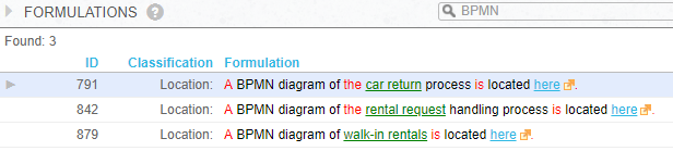
It is possible that these formulations do not use the letters 'BPMN' but only, for example, the word 'diagram', or only words describing what the diagram is about. The ending "... is located here" is necessary for a formulation to represent a diagram.